Home Brew 2.4 GHz Audio/Video Scanner

   Hi scan freqs, here's a crude but effective scanner for you to use to tune into those 2.4 GHz video camera/senders out there. Since I don't have all the time in the world to teach you how to use a soldering iron it is assumed that you already have some basic knowledge of doing so, knowing how to read a schematic and all those other cool details.

   I'll try to keep this whole thing short. It all started out when the first 2.4 GHz video senders were being sold on the market. You know, those wonderful devices that replaced that old Rabbit system on 900MHz that would allow you to watch your
VCR in a different room? But as soon as they became more popular, especially being used on surveillance cameras, I figured that I wouldn't be wasting my time with this thing and driving around the neighborhood with a TV glowing out my windshield. In the process of trying it though my partner-in-crime and I soon realized that switching to each channel was not only painful but very annoying and kept us from making sure we were able to receive all possible transmissions in the general area as we drove by. Hence, the 2.4 Gig scanner was finally born (at least for us).

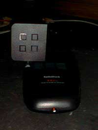
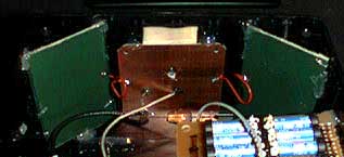
   Please keep in mind that there is a budget to such activities and I believe that includes most of the people reading this. So the following is a crude design, very crude..  First you need to get yourself one of those 2.4 GHz Audio/Video receivers by Wavecom or some other brand name such as the Radio Shack model to the right. I purchased this one as a combo unit for $50 (it was a discontinued model, # 15-1971) so getting one cheap is possible. The average price is $100 for a combo unit of a transmitter/receiver so watch it that you don't get too burned when buying one, especially on the net. Be sure it's a 4 channel model. All we need though is the receiver for this application, duh obviously, so if you want to save money just get the receiver. Now on to the real project...    Since I modified the above mentioned model this will be the example used here. Of course other models may vary in their channel switching methods internally, but I really don't think there will be a difference. If so, then you'll have to figure it out, it's not that hard... Inside you will have a four position switch. On this switch there will be two

rows of 6 contacts, making 12 total. Now every time the switch is moved it will be using 2 of the contacts on each row. The crude layout of each contact is posted below along with a chart to show which contacts should be connected going from so-called channel A through D. Reed relays were used in this application for their quiet switching, but more importantly for higher speed compared to regular ol relays. Of course you could go a transistor route but would cost more and in the end you don't want it to go ultra fast because you want to actually see what your receiving and the circuitry won't stabilize well going (rough guess) 40 channels a second. I know, I know....there are only 4 channels but you get the point. Now we need a way to switch these relays. A schematic provided by Radio Shack fit the bill quite well and is also posted below along with a timing circuit I decide to use to clock it instead. Now here's the hard part, this is where you are on your own.....sorry. I had to make this in my own weird fashion to prepare for future updates to it so to post "exactly" what I did won't make sense and I really don't have the time to lay it all out anyway. But wait...what about the antenna...ah yes, the pain in the ass antenna. As you should already know we are dealing with microwave frequencies and the supplied squared antenna, although will work, does not work well for real clear reception and long range. So here is where this scanner gets VERY crude.

   Since I didn't want to spend over $100 on a premade Yagi plus I wanted to try and keep things as omnidirectional as possible I decide to do a trial and error thing. So far I found this to work quite well. There are 6 total antennas. I positioned the antennas as seen to your left. One is the original antenna that came with it taken out of its plastic casing. From there you can see two green boards at about a 45 degree angle. These are from a salvaged PC board that
was being used as an antenna for the US Coast Guard (no questions please). All it is though is a double sided PC board without any holes drilled in it. You can obtain the same thing from Radio Shack that is advertised for etching your own boards. I cut the antenna down and made two pieces into 3 inches in length and they were already 2 inches in width. After you have them cut and ready you will need to solder wires to both sides of each board. Next you will need to create continuity between them all so solder some short wire to each one like the red wire seen between them. I did notice that these wires needed to be short but not very short, adding extra just decreased range. I did leave a little slack though and let the extra stick out between the original antenna and the green one. This acted like an ol  UHF Yagi in some cases depending on where the signal was coming from and proved to be effective, hence added to the signals gain. As for a ground plane I didn't get that far due to it blocking the signal in this current antenna arrangement, so I will need to redo this design for better gain. Now this is by no means a correct design by mathematical standards but really worked and saved a lot of money. Also, be sure to try and place the original coax coming from the receiver in the middle somewhat, it helped.... Now if you study the crude design you'll see how the signal is captured from "almost" all directions, including reflections from nearby metallic objects adding to the gain (but at times it might hinder reception so you'll have to figure out how to move it around when you get as close as you can get to the transmission).

  Version 1.0 of this design looks like this. You have 4 blue LEDs for the channel indications, the power switch, power input, RCA jacks for the A/V connections including the RF output in case I wanted to use channel 3 or 4 on a portable TV that doesn't have composite inputs, a 4 pin din connector for connecting a remote control for pausing/switching and on the side you'll see the scan rate knob. This is just version 1 so bear with me on the looks of it.   Other features coming for it, at the least, is an automatic stop feature much like a squelch and
a signal meter to get the best possible signal. I kind of like the looks of it though, it looks like a mysterious black box and sits like a radar detector on the dash of the vehicle used when in pursuit of that secret camera.


Here is your switch contacts....sorry, best I can do for now with the little time I have to spare.

Channel A - 1/3 and 7/9
Channel B - 2/4 and 8/10
Channel C - 3/5 and 9/11
Channel D - 4/6 and 10/12

Notice that contacts 3, 4, 9 and 10 are used twice, these act as commons in a way. Doing that will narrow it down to 4 relays.

This was used for the switching, remember this is only a guide and must
be modified using transistors instead of LEDs to activate the relays.


This is the clocking circuit used in my design but use
what you want, it doesn't need to be fast.